Neuron Tracing with the Filament Tracing Wizard in Imaris
This guide describes the simplest way to perform automatic neuron tracing using the Imaris filament tracing wizard. Whilst this method is easy to use and gives excellent results it is important to be aware that several steps may require a long processing time (10-20minutes), especially on large images.
As the algorithm relies on local intensity contrast to trace filaments the use of a image filter will reduce noise and minimise tracing errors. For most cases, applying a median filter (found under under Image Processing) before starting the filament workflow will ensure best results.
If you intend to accurately count spines it is recommended to deconvolve your image first using Autoquant (available on Imaris Workstation #1)
— A video showing each step of this workflow is available at the end of this guide —
1. In surpass mode, add a new filament to the surpass scene.

2. Choose the AutoPath (no loops) algorithm in the drop down menu. This algorithm prevents looping back on neuronal processes . Since this algorithm relies on local intensity contrast to trace the filaments use of a filter (Gaussian Filtering, under Image Processing) will reduce noise and minimize tracing errors. Also select calculate diameter of filaments from image is enabled. Then press the blue arrow to go on to the next step.
NOTE: If you intend to accurately count spines it is recommended to deconvolve your image first using Huygens Deconvolution

3. If you only wish to trace one neuron in an image that contains several use a region of interest to save time. You can also create several regions of interest to trace selected neurons. If required, click the Segment a Region of Interest check-box.
3. The next step is used to define the size of the cell bodies of the neurons you wish to trace and the thinnest diameter of the dendrites you wish to detect. Using a 10µm starting point and 1µm thinnest diameter will usually give good results – once you have entered some parameters click through to the next step. (These parameters are not necessarily important for the final result as explained in the next step)
4. Imaris will automatically detect the cell bodies and dendrites. However, it often places far too many points in the dendrites and can inaccurately find cell bodies – to override the automatic detection drag the yellow region in the adjustment graphs all the way to the right until no cell body or dendrite points remain (see images below).


5. It is now possible to place the cell body and dendrite points manually. The fewer points you place the faster the software will be able to find all the dendrites.
First, to mark the cell body, ensure you are in select mode then scroll the mouse wheel until the selection box is roughly the size of the cell body, move the cursor over the cell body and shift-right click to place the point.

Now, place a single point at the end of each dendrite – it is not necessary to place points along the dendrites, only at the very ends. To do this, readjust the selection box in select mode until it is similar in size to the dendrites then shift-left click to place dendrite points. The software will automatically figure out the correct depth to place the point regardless of the angle you are viewing from. If you place a point in the wrong place accidentally simply click on the point again and it will disappear. This step will involve you switching from select mode to navigate mode repeatedly to view and place points – remember to use the escape key to do this quickly.

Once you have placed all the necessary points click the blue arrow to move on the next step. The processing for this step may take ~5-10minutes to map out all the dendrite paths.
6. Imaris will have detected all the dendrite paths and in this step asks you to set a threshold – this threshold is used to determine the diameter of the dendrites based on the fluorescent image. Choose a level that you believe best represents the actual structure of the neuron and move on to the next step.
Depending upon the size of the image this step may also take several minutes of processing time.

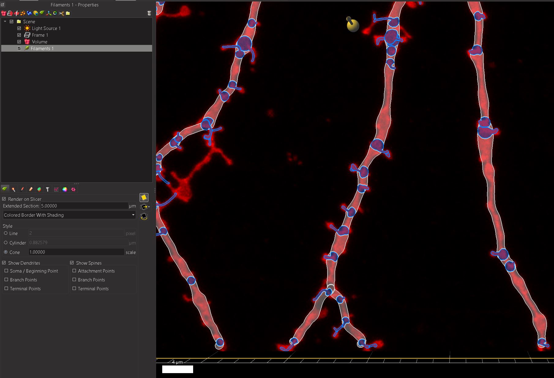
7. You will now be presented with a traced neuron with dendrite diameters comparable to those seen in the original fluorescence data.
8. The remaining steps of the wizard are concerned with detecting spines on the neuron. If you do not wish to detect spines deselect detect spines and finish the workflow.
Otherwise, enter a reasonable thinnest spine diameter (1 to 0.3µm) and maximum spine length (1 to 4 µm) and go on to the next step of the workflow.

9. After detecting all the spines you can adjust the histogram to remove or add spines to the tracing. If you can see spines which aren’t being detected or perhaps seeing too many spines try adjusting the parameters in the previous step.
10. Finally, adjust the threshold to determine the diameter of the spines based on the fluorescent image.
11. Once you complete the workflow you may find you need to remove some errors in the tracing, these may be extra spines which don’t exist, or an incorrectly traced dendrite. You can correct these errors and add in additional spines and dendrites very easily using the manual edit tools described in Imaris tutorial: manually editing traced neurons
To review the filament tracing workflow please see the video below:
The movies below demonstrate what is possible once neurons have been traced using the Imaris filament tracer:
Example 1: Large Neuron in collaboration with Ben Sivyer (Williams Lab)
This movie shows the final neuron (comprised of 12 separate stacks) following alignment in XUVstich and direct import into Imaris – (a guide for how to do this will be published shortly)